
Definition: The main function of switchyard is to transmit & distribute the power at incoming voltage from the generating station and provide facilities of switching by the help of switchgears. Earlier we have explained about the various types of switchgears in our previous article.Switchyard is the point in the power network where transmission lines and distribution feeders or generating units are connected through circuit breakers and other switchgears via bus bars and transformers. Switchyard acts as interface between the power plant electrical system and electrical grid.
Types of Switchyard
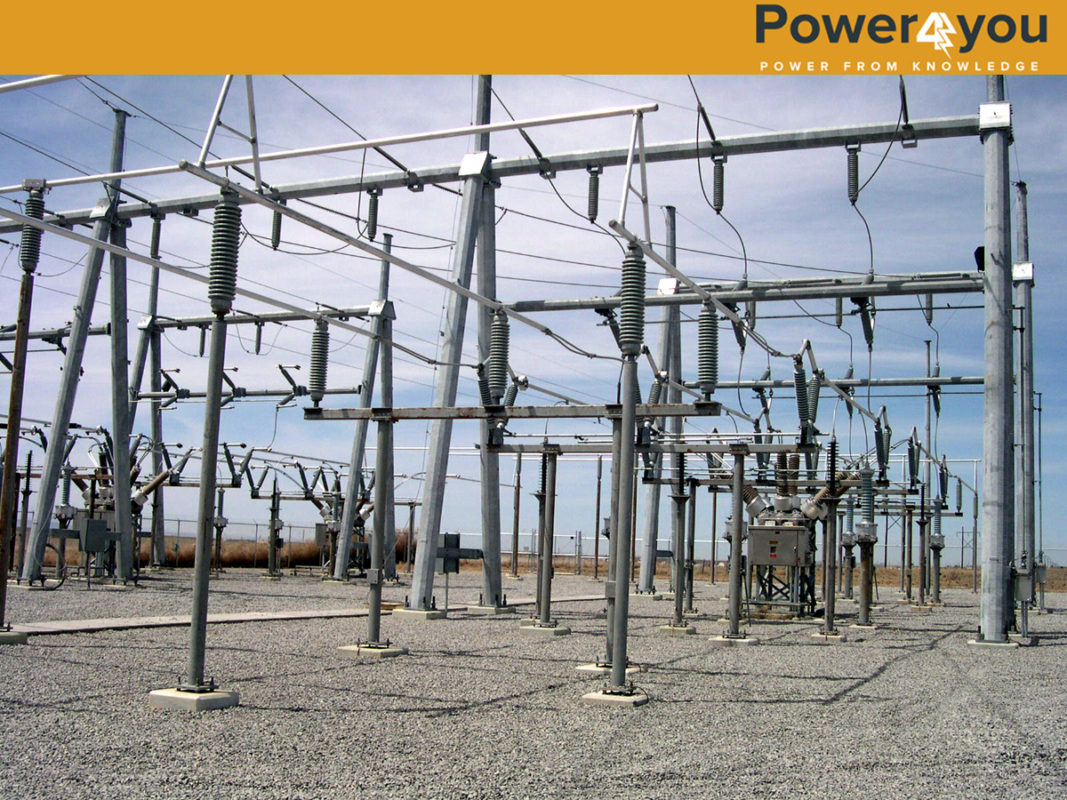
- AIS (Air Insulated Switchyard): This is the most common type of switchyard; here the switchyard is present outside and open to the atmosphere. The high voltage lines are isolated by the air, for that reason they occupy more space as compared to the GIS.
- GIS (Gas Insulated Switchyard): This type of switchyard is generally found where the space available is very less and they are generally located inside a closed room with proper isolation. The high voltage cables are kept inside the duct with insulation.
Components of Switchyard
Gantry Structures: Gantry structures are made of steel and are used to support high voltage conductors throughout the substations that interconnect sections of electrical equipment. In general there are two types of gantry structures and out of them Tubular gantry is mostly used in switchyards as it takes lesser time for installation and easy to install.

Bus-bar: Bus-bars receive the power from incoming circuits or we can say a grid and deliver the power to an outgoing Circuit. It can be single phase or three phases, but most of the cases it is 3-phase and one bus consists of 3 conductors(R-Y-B).There are also various types of bus bar arrangements depending upon their requirements. The various arrangements are mentioned below:

Single Bus System: This type of bus arrangement is the cheapest and the simplest one. In this scheme all the feeders and transformers are connected to only one single bus as shown below. The major disadvantage of this kind of system is that for the maintenance of the breakers and other equipment we have to isolate all the systems and keep it in offline. This scheme is generally employed for the gas insulated switchyards and another disadvantage is that if you are going for maintenance then the respective transformer or feeder should be disconnected.
Single Bus System with Bus-sectionalizer: In this type of arrangement the main bus is divided into two different circuits by the help of a circuit breaker. The advantage of this kind of arrangement is that if one section of the bus bar is under maintenance then the other part of the system, which is isolated by the bus-coupler or bus-sectionalizer, is kept energized, but here also if we are going for maintenance on any breaker then the respective feeder or the transformer has to be disconnected.
Double Bus System: In this arrangement, two identical bus bars will be there, one as Main Bus-1 and the other as Main Bus-2.Here both the buses are connected through a bus coupler. The bus coupler does two works during line charging it matches the voltage level of both the lines and connect both the lines. Here the flexibility of the system is increased as another bus-bar acts as a backup for the other bus-bar, but here also without any interruption we can’t go for the maintenance.
One And A Half Breaker Scheme: This is the most advanced and widely used scheme in modern power plants. In this type of scheme
Two feeders are connected to two different buses through their circuit breakers respectively and these two feeders are connected by a third breaker as a tie breaker. During failure of any feeder breaker, the third breaker comes into play and transfers power to the other feeder. This scheme increases the availability of the feeder during maintenance or failure of the other feeder. If there is some fault on the Bus-1 then also without tripping the units we can continue the power flow by the help of the tie-breaker.

Insulator: The insulators mainly serve two purposes. First of all they support the conductor and confined the high current of the line to the conductor. The most common material for the manufacturing of insulators is Porcelain. Below mentioned are the types of Insulators used in switchyard,
- Pin Insulator
- Post Type
- Suspension Insulator
- Strain Insulator
Post type and strain type insulators are mostly used in switchyard.
Surge Arrester: This will protect the equipment from transient, surge and high voltages. They are generally connected in parallel to the equipment to be protected and function to divert the surge current safely to ground.
Isolator: Isolators are generally no- load switches which are used to isolate the electrical lines during maintenance. They are only operated for isolation after the circuit breaker is operated. They are operated by means of a motor present below the isolator assembly.
Earth switches on Isolator: Earth Switch is used to discharge the residual charge on the circuit to the earth safely. Earth switch is mounted on the frame of the isolators. After the equipment is isolated then the earth rod is connected so that the residual charges present on the device will be grounded. This is mainly done for safeguarding human life from getting a shock.
Wave trap: Wave trap is a resonant circuit connected in series with the HV transmission line to prevent the transmission of high frequency signals. The communication wave is having a high frequency of 150 KHz to 200 KHz and the electrical power has a frequency of 50 Hz. So to avoid the communication waves to travel to the electrical equipment we are using this Wave-trap. It creates a high reactance path for the High –frequency signal and blocks it. We are employing these Wave-traps is due to the use of PLCC (Power Line Carrier Communication).
PLCC: PLCC stands for Power Line Carrier Communication. This technology is used in all sub-stations for communication with other sub-stations. The information regarding the generation and other parameters are transmitted to other sub-stations or grid by the help of this PLCC. By the help of PLCC, we are avoiding the use of an extra wire for communication and the information flows through the transmission lines and it is much faster than any other medium.
Circuit breaker: A circuit breaker is equipment which can make and break a circuit under normal as well as during fault conditions. It is operated during on load condition and the arc generated while opening the circuit is quenched by a strong di-electric medium. The most widely used arc quenching mediums for HV Lines are Vacuum and SF6 Gas.
Current transformer: Basically this is a step down transformer which is used for measuring purpose as well as protection purpose. For both these purposes the CTs are designed with different types of core. For measuring purpose, the CT saturation point is given at ankle point on the characteristic curve between the Flux (⌀) and current (i) and for the Protection purpose the saturation point is given at ankle point of the curve. The CTs generally have a ratio of 100:1 or 200:1 so that they will reduce the transmission line current to a very lower value suitable for measurement and relay protection (around 5 to 4 Amps).These are connected in series with the transmission line.
Potential transformer: Potential transformers are used to step down the line voltages up to measurable quantity i. e 110v from any voltage level (for measurement of voltage).They are connected in parallel with the transmission line.CTs and PTs almost look alike, but depending upon their connections we can distinguish them.
Protective relay: A protective relay is a device that detects the fault and initiates the operation of the Circuit breaker to isolate the faulty element from the rest of the system. Whenever there is a fault in the bus,the relay senses it and gives the command to the circuit breaker and the circuit breaker is operated. The relay receives the command from the instruments transformers (i.e CTs & PTs).The total relay circuit is given below,

(Circuit Diagram for the Relay & Circuit Breaker(CB))

Hello ~ Awesome content ~ Thank You
Thank you sir for the feedback.
hi sir thnk u,frm santosh gain some basic knowledge about switch yard becoz of uu
we really appreciate.Thank you for your support